3D slicers determine how a model is built and instruct the 3D printer how to print it. Learn all about this essential software in 3D printing.
A slicer is a program that converts digital 3D models into printing instructions for a given 3D printer to build an object. In addition to the model itself, the instructions contain user-input 3D printing parameters such as layer height, speed, and support structure settings.
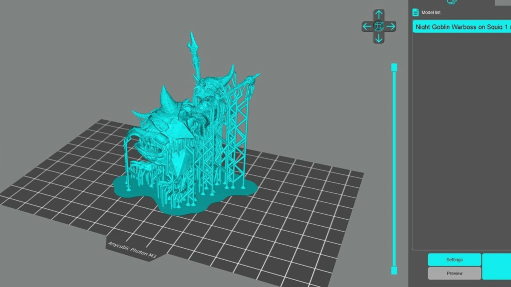
Any 3D printing technology creates 3D objects by adding material layer by layer. The Slicer software is therefore aptly named because it effectively 'slices' 3D models into many horizontal 2D layers that will later be printed, one at a time.
In this article, we'll discuss the role of slicers in 3D printing, detail how 3D slicing works for FDM and resin, and finally conclude with slicing in other 3D printing technologies. Let's start!
Computer-Aided Manufacturing (CAM)
Although not usually associated with slicing software, computer-aided manufacturing (CAM) is useful in our understanding of what a slicer does. CAM is computer software that assists, facilitates or automates manufacturing processes. In effect, it serves as a bridge between digital 3D models (produced by computer aided design or CAD) and manufacturing systems by converting drawings into instructions for the machine to execute.
These instructions are transmitted in the form of command lines, commonly referred to as computer numerical control (CNC). As the name suggests, the commands entered control all aspects of the machine, including movement speeds, temperatures, and cooling. Although there are many different ways to "talk" to these machines, the predominant language is G-code, which is used in various types of manufacturing systems.
Although 3D slicers are not strictly categorized as CAM software, they perform the same function in the 3D printing process in that they output digital files containing detailed instructions for the printer to execute. In most cases, as we will see later, they even generate G-code commands.
3D slicing procedures may seem simple to anyone who has printed a 3D model. But what's really going on behind that tidy user interface? Let's take a look at what we need to have a successful slicer experience.
Requirements
To successfully prepare a model for 3D printing, the slicer requires two different inputs: the 3D model itself and the set of print parameters that tell the machine how the actual printing should be done.
3D models
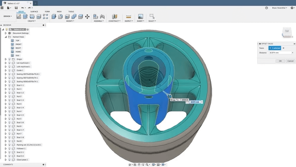
You can create digital 3D models using a wide variety of CAD software, ranging from the artistic and open source Blender to the professional and highly technical SolidWorks. The problem is that each digital file created with a particular CAD tool has a specific format, such as "Blend" (.blend) for Blender and "part" and "assembly" (.sldprt and .sldasm) for SolidWorks.
If 3D slicers were to handle all these different formats, they would require a huge support base, but even so, they certainly cannot cover all modeling software. For this reason, a standardized file format is used. The one most commonly associated with 3D printing is STL (.stl), which is exported by most 3D modeling software programs.
3D printing parameters
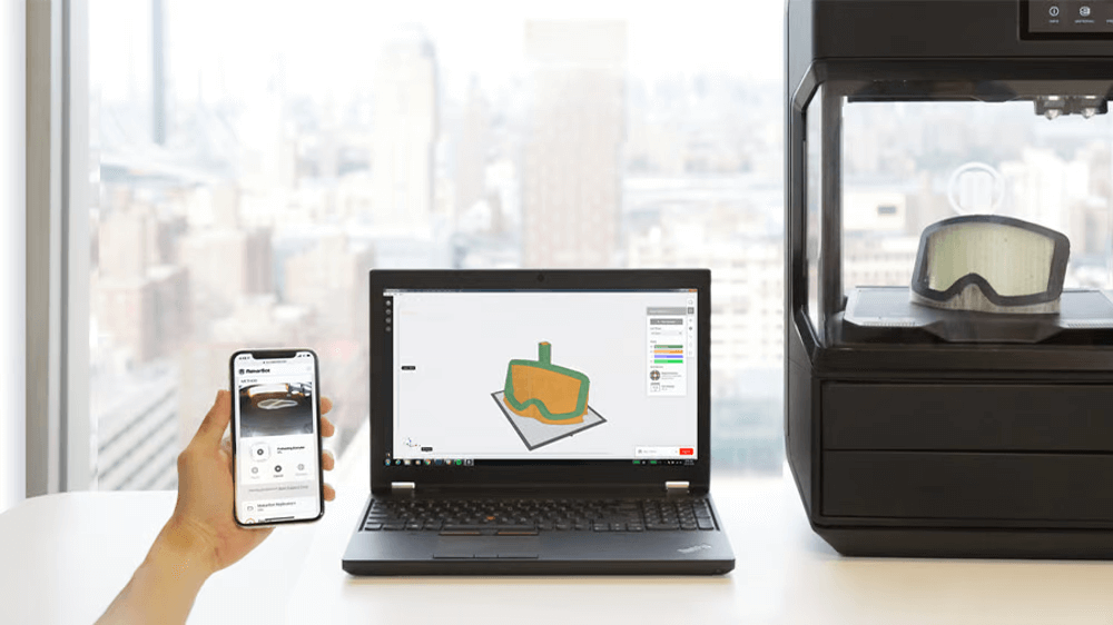
With the 3D model in a format the slicer can understand, the next step is to provide print details such as layer height, speed, part positioning, and several other production-related settings. These user-entered values are defined before printing.
The 3D model can also be partially modified during this step. You can change dimensions using scaling functions, and parts can be partially or fully hollowed out, filled with fill patterns, and wall thickness values provided. This step also includes enabling support structures, which is one of the most practical features of a 3D slicer.
3D printing parameters will vary depending on the type of technology (FDM or resin-based), as well as the type of material (different types of FDM filaments require different settings, for example), the object to be printed, and its intended purpose. So let's see what comes into play for each.
FDM slicing
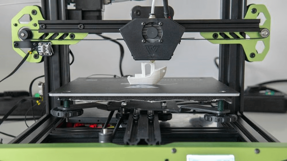
Fused deposition modeling (FDM) is a material extrusion technique where a print head moves in two different directions (X- and Y-axes) while the plastic filament is melted and pushed through the nozzle to create a 2D layer. This process is repeated until, layer by layer, the 3D object is complete.
FDM printers rely heavily on motion to build a 3D object, with the fine, multi-axis control necessary for accurate printing. Once the 3D model and print settings are defined, the slicer will process these inputs and generate a G-code file that is then uploaded to the 3D printer.
The last step is done entirely by the internal algorithms of each 3D slicer, which means that it is not related to the user and that each slicer will do this differently. In simple models, the differences between the slicers may remain invisible, but in more complex ones, they will certainly be noticeable. Certain slicers may work better with certain 3D printers, but there is no hard and fast rule to know which one will work best for you.
Many 3D slicers are available for FDM, some of which are free. While Ultimaker Cura is perhaps the most popular in the open source community, Simplify3D is the premium (and expensive) choice.
Cutting resin
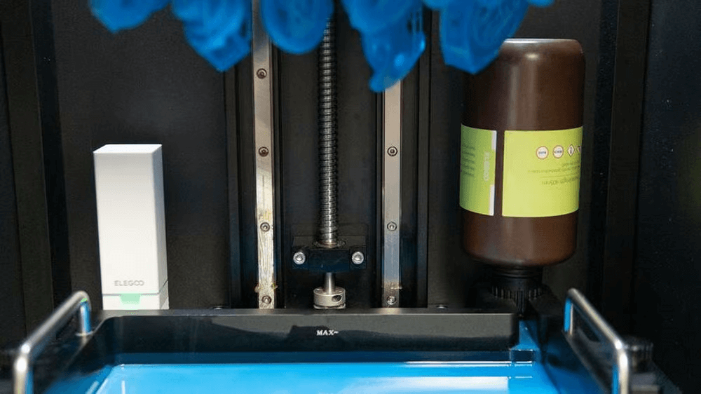
Bath polymerization uses UV light in various forms to harden and solidify liquid resin in layers. Once a layer has cured, the build platform is moved to allow the fresh resin to fill and form the next layer until the 3D part is created.
This 3D printing technique relies less on motion than FDM. For "true" SLA printers, the deflecting mirror rotates to direct a UV laser beam at the resin, outlining and shaping each 2D layer. With DLP and MSLA 3D printers, the only real movement is done by the build plate, which moves exclusively along the Z-axis during the entire printing process.
One difference from the FDM printing process is that resin printers do not use G-code in their source files. In fact, most desktop resin 3D printers use their own format and therefore their own slicing software. However, there are third-party slicers available, such as ChiTuBox and FormWare, that are compatible with many desktop printers.
Slicing for resin is somewhat similar to FDM, but the parameters of 3D printing differ. Rather than nozzle temperature or cooling, resin settings include exposure times and lift speeds. However, layer height and features such as support structure distribution are also present in the resin, just as in most 3D printing technologies.
A piece of the rest
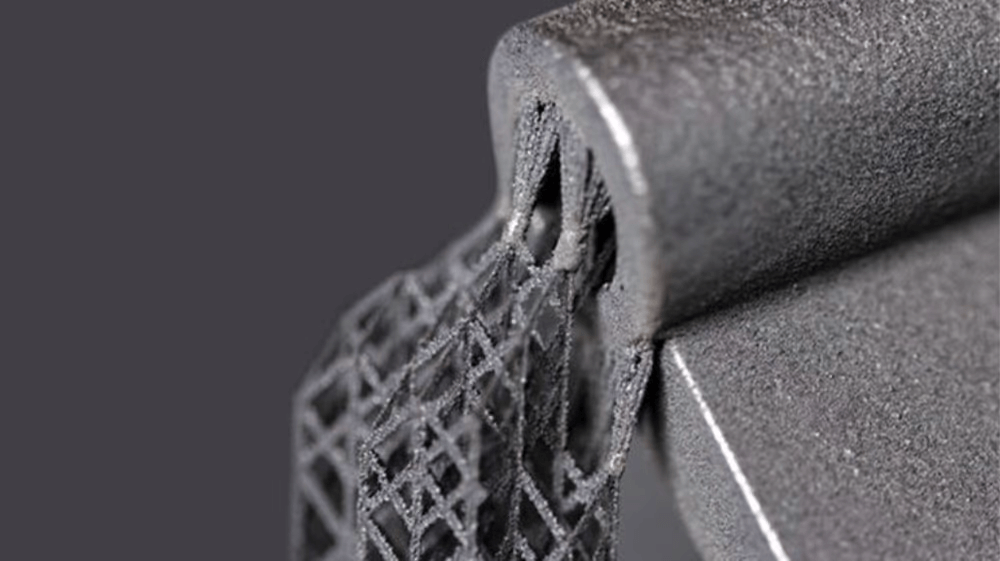
Other 3D printing technologies such as SLS, SLM or even EBM and bonding jet cutting require specific slicers due to the added complexity and variety of their processes. For example, an SLS system from one manufacturer will not perform the same as its competitor, which is why most of these machines use official manufacturer's slicing software.
However, the Belgian company Materialize has a whole suite of software that can be used in 3D printing technologies, including a powerful 3D slicer called Magics. This software can be enhanced by various post-processing modules that output the appropriate cut file for specific machines with different 3D printing processes, including metalworking machines such as GE's Arcam and Concept Laser and HP's material jetting systems.
0 Comments