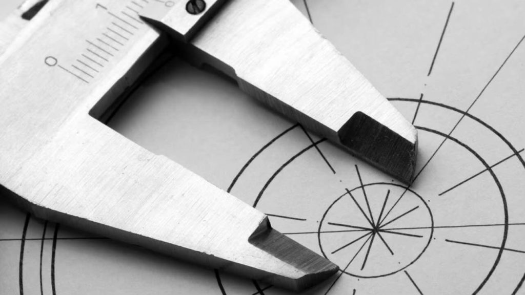
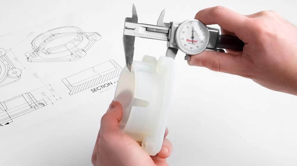
For engineers, tolerance is critical. Learn how to minimize the inevitable inaccuracies of 3D printed parts.
When designing or manufacturing practical and functional parts, their performance often depends critically on accurate dimensions. For example, a ruler wouldn't do its job very well if it wasn't straight and marked at precise intervals. Two Lego bricks wouldn't fit together if their dimensions weren't right, and a 3D printing nozzle wouldn't extrude accurately if its hole diameter was inaccurate.
Tolerances help avoid these types of problems by establishing the acceptable level of dimensional inaccuracy. Tolerances are instructions from the designer to the manufacturer as to how much a given size can deviate from its nominal designation, recognizing the fact that perfect size production is often impossible to achieve.
What are tolerances?
For our purposes, accuracy can be defined as a measure of how close a measurement is to its "nominal" design. For example, if the part design says it should be 5 cm long, a 5.01 cm long version is more accurate than a 5.1 cm long part. Obviously, a part that is exactly 5.00000… cm long would was most accurate, but this is usually not possible in most manufacturing processes. The fact is that nothing around us is exactly ; realistically everything is slightly larger or smaller than its nominal design. The amount by which it varies depends on the purpose and method of production.
The way to overcome this problem is, as with any problem, to first acknowledge it, for only then can a solution be found. And the way to solve this measurement problem is to design with tolerances. Going back to our 5 cm part, if the tolerance is 0.1 cm, then any result of 4.9-5.1 cm is considered acceptably accurate. Naturally then, in addition to accommodating manufacturing inaccuracies, setting tolerances also means ensuring that the parts will function correctly anywhere within that dimensional range.
It should be noted that tolerances generally refer to part dimensions, not machine performance. The quantities that determine the permissible operating range of the machine are defined in metrology as "accuracy", "precision", "repeatability", etc.
Now that we understand what tolerances are, let's look at what defines tolerances for a part: fit.
Types of assemblies
In most applications, the joint between two parts must perform a specific function. Let's illustrate this with an example.
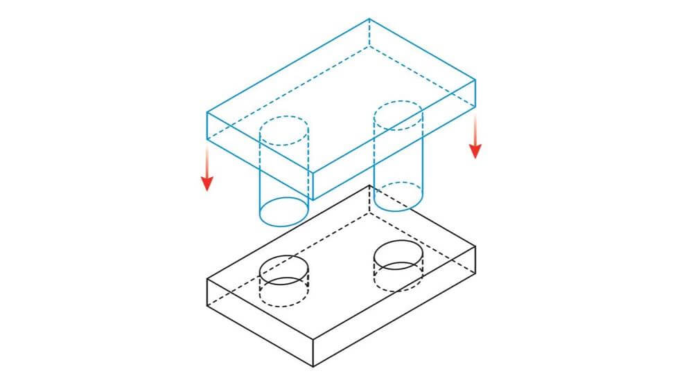
Consider a round shaft designed with a nominal diameter of 50 mm that must fit into a circular hole with a nominal diameter of 50 mm. In practice, there are three options for how these two parts can fit together:
- The diameter of the shaft is significantly narrower than the diameter of the bore, say 49.8 and 50.2 mm respectively. In this case, the shaft will easily slide in and out of the hole and rotate inside it. This leads to what is known as slack .
- The diameter of the shaft is the same or slightly wider than that of the bore, say 50.2 and 49.8 mm respectively. The shaft won't go into the hole without a lot of force, and once it goes in, it probably won't come out without breaking parts. This type of fit is widely used when high concentricity and mutual movement are required (such as attaching a shaft to a bearing). This is known as interference fit .
- The diameter of the shaft is slightly smaller than that of the bore, say 49.9 and 50.0 mm respectively. The shaft will enter the bore with minimal effort and maintain relative concentricity. That's what it's called transitional assembly.
In reality, each of the fit types is a spectrum of allowable combinations; the above dimensions are only indicative. To choose the right fit and design, there are several international standards (like ISO tolerance), but we won't go into that in this article.
However, the type of assembly must be determined before tolerances are set. If properly set, two interacting parts will continue to function as intended no matter how close they are to the positive or negative limits of the range.
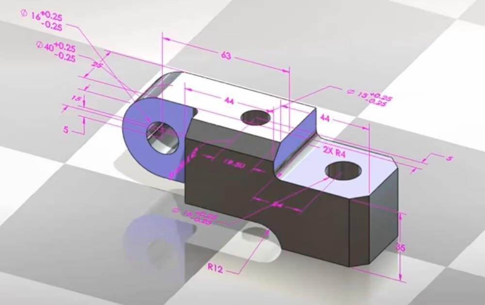
3D printing issues
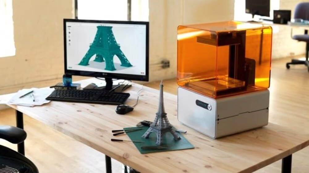
The type of fit (and therefore the dimensions of the mounting parts) must be consciously decided while the part is still in the design phase. What most affects the exact values of the specified dimensions and tolerances is the method of manufacture. For example, you can't expect to get similar results with a chainsaw as you would with a fine woodworking chisel.
With 3D printing, there are often some missing links from the conventional design and manufacturing process. Typically, a designer designs the parts and submits them to the manufacturer with the required tolerances for the part. It is then the responsibility of the manufacturer to meet these tolerances. However, in 3D printing, since the digital model is exported directly to STL and then printed, any information about the required tolerances is not applied in the manufacturing process. Nor the chainsaw ( Slicer) , nor the printer will know the tolerances from the designer. This means that the user will need to control both the design and the printing process to achieve the required tolerances.
Causes of FDM inaccuracies
Aside from design errors (which are endemic to any manufacturing process), there are several key causes of inaccuracy that are inherent in 3D printing, and FDM machines in particular.
SOFTWARE ERRORS
When a digital model is converted to STL, some details are inevitably lost. For example, round objects are faceted and converted to straight surfaces and vertices. However, the higher the conversion resolution, the less dimensional error is introduced into the part.
Slicers may introduce their own errors depending on their specific algorithms and settings. How the slicers interpolate the vertices of an STL file will greatly affect how the G-code will look and therefore how the printer will behave.
MACHINE INACCURACIES
There are several ways that the 3D printer itself can cause inaccuracies in a printed part. Stepper motors have limited resolution, so the accuracy of the motion path is only as accurate as the motors maximum resolution. In addition, typical FDM 3D print engines lack a position control loop, so small position errors can accumulate over long print jobs. Most motor drivers also have a thermal protection feature that stops them from running if they overheat, which can cause the motor to skip steps. The e-steps of the stepper motor are also a crucial measure that can cause dimensional inaccuracy if not calibrated correctly.
If the printer axes are not adequately orthogonal to each other, structural inaccuracies will occur. Imagine trying to draw a rectangle with an axis that is not perpendicular - you end up with a parallelogram. Then, every time the axis of motion changes direction, there will be some play. The lower the tension in the belt system, the more pronounced the slack. Straps also introduce other timing problems, such as creep and elongation, which not only reduce accuracy, but can also cause slippage and missing steps.
Since the printer prints a line of threads, it is expected to create a uniform width. However, the beginning of the print line can be thinner and widen to the end of the line as the nozzle pressure increases. This may be exaggerated when cornering. Overall over-extrusion of the filament will also result in a wider print line, which can result in over-sizing, with the opposite effect of under-extruding, and the quality and condition of the filament can lead to additional extrusion problems.
Finally, incorrect initial Z height can cause "elephant foot" when the first layer spreads wider than subsequent layers.
Designer solutions
Once you understand the possible causes of inaccuracies in your printouts, you can take proactive precautions to eliminate them as best as possible. In practice, you can't expect a regular FDM printer to nail down to 100 microns. This means that all your dimensions should be designed with the assumption that they may come out larger or smaller by this value.
With pre-assembled parts, you will need to design them so that even with uncontrolled dimensional error, they still work together as designed. In almost all cases, this will mean that if you have two parts that need to fit together, you will need to design one part smaller than the other. For a standard 0.4mm nozzle, here are general rules of thumb for fit based on hole and shaft fit, although you'll need to experiment and learn the actual values for your printer.
- Clearance: A difference of 0.5 mm or more between the diameter of the hole and the diameter of the shaft. This results in a theoretical distance of at least 0.25 mm between the shaft and the hole.
- Transitional fit: 0.15-0.4mm difference between hole diameter and shaft diameter. This results in a theoretical distance of 0.08-0.2 mm between the shaft and the hole.
- Interference fit: A difference of about 0.1mm or less between the bore diameter and the shaft diameter. This results in a theoretical distance of 0.05 mm or less between the shaft and the hole.
Since these rules refer to the difference between parts, they can also be used for non-cylindrical parts. When considering non-cylindrical mating parts, such as a square hole and a corresponding square boss, the aforementioned rules can be applied to the difference between the nearest assembly planes. For example, to get a clearance suitable for a 30mm square bar, design the hole to maintain a gap of 0.25mm (ie 30.5mm square).
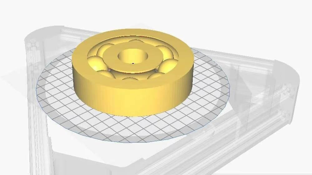
Another key guideline is to consider the orientation of the part so that maximum quality can be achieved. Holes print best horizontally (parallel to the XY plane of the printer). If you need to print a vertical hole, use the teardrop technique, where the top of the hole is designed in a pointed shape rather than completely round. This eliminates any inaccuracies caused by thread overhang when closing the top of the hole.
In addition, due to the multi-layered nature of FDM 3D printing, vertical features are generally less accurate as they can be as fine as the layer height. The horizontal (XY) function is usually more accurate as they are only limited by the resolution of the stepper motors and the belt as explained in the previous sections.
Software solutions
There are several software solutions that can help increase the accuracy of your printouts. When cutting a part to print with maximum accuracy, you should typically use slower kinematics (velocity, acceleration, and cadence), smaller layer heights, and active part cooling. We recommend print speed below 60mm per second, acceleration less than 3000mm 2 /sec. and sudden movement less than 15 mm / sec. for most desktop printers.
There are also some unique features in the slicer settings that can help improve dimensional accuracy. The following examples are for Girl, but most chainsaws have similar characteristics.
- Outer before inner walls /External before internal walls/: By printing the outer walls first, you can theoretically improve dimensional accuracy by not getting hit by the inner walls or infill.
- Coasting /Inertia/: This feature causes the printer to stop extruding towards the end of a stroke and instead rely on the residual pressure in the nozzle to print the remainder of the stroke filament.
- Horizontal expansion /Horizontal expansion/: With this function, you can increase or decrease all dimensions of a part by a certain percentage. Ideally, this can help fine-tune the dimensions of the print, but it's only really useful if the entire print is too small or too large. If the overall footprint dimensions are acceptable and only holes need to be corrected, for example, a different method should be used, such as the Hole horizontal expansion function.
After slicing, the function linear advance in Marlin and some other firmware adjusts the thread flow according to the intended print movements. The linear advance function anticipates the change in nozzle pressure that can cause inconsistent extrusion and adjusts accordingly. This converts the irregular line width into a more uniform line, which improves the accuracy of the footprint dimensions.
Linear advance has a similar effect to the momentum settings in your slicer, but is generally easier to set up. To use this feature, you will need to enable it at the beginning of the print process and provide a K value to set how much the printer should adjust the flow (this value can be found experimentally).
Machine solutions
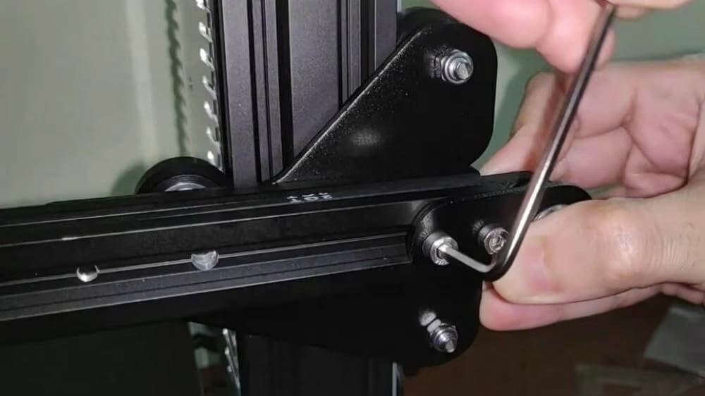
Perhaps the most important way to achieve maximum print accuracy and stay within tolerance is by calibrating the printer. A poorly calibrated printer will result in parts that are not straight, do not have the correct dimensions and do not fit together. On top of that, always remember that no hobby grade desktop 3D printer is perfectly and fully calibrated from the start, even if they come pre-assembled; they will require additional calibration over time as a routine maintenance operation. Professional-level machines may compensate for this somewhat, but still need regular maintenance and calibration.
Since poor calibration can render all your design and cutting efforts for naught, the importance of machine calibration cannot be understated. The most important elements to calibrate are the extruder and the E-steps, and it's always vital to start with a good first layer.
It's also important to choose good quality nozzles and filaments, as the dimensional accuracy of your part is largely dependent on the assumption that the extruded filament is actually the diameter it needs to be. Significant deviations in filament diameter or worn nozzles will have an immediate impact on the possible tolerances of your prints.
Post-processing solutions
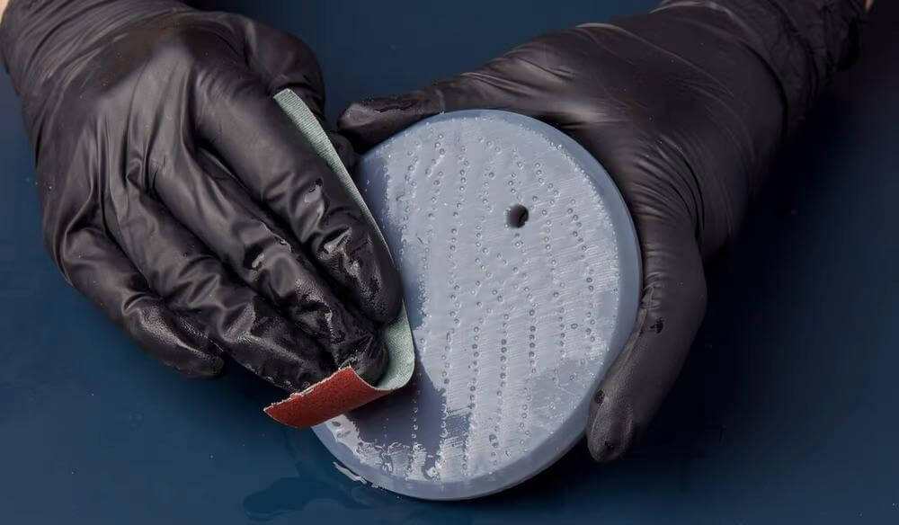
Even after all the calibration, proper design, and special cutting configurations, sometimes parts will still be out of tolerance. In this case, they will need to be aligned through post-processing.
There is no shame in accepting the need to post-process a part. Even with highly accurate CNC machining centers costing hundreds of thousands of dollars, some post-processing of parts is sometimes necessary to get them to fit and meet specifications.
It is important to note that post-processing usually refers to subtraction methods, so it is usually more suitable for parts that are large in size than smaller ones. Here are some key tips to get your parts down to design dimensions.
- Continue measuring the pieces as you work until you reach the desired dimensions.
- Drill or calibrate any 3D printed hole.
- Try to avoid supports if possible. It is much easier to re-drill a hole than to try to pull out small supports with a pair of pliers.
Finally, at some point we have to recognize that certain Geometric Dimensioning and Tolerancing (GD&T) requirements cannot be easily met at the DIY level.
0 Comments