3D принтирането на зъбни колела е възможно, понякога дори за предпочитане! Научете се лесно как да правите 3D отпечатани зъбни колела, които отговарят на вашите нужди.
Зъбните колела са един от най-основните компоненти за предаване на движение в механични възли. Те датират най-малко от 4-ти век пр. н. е. в Китай и днес могат да бъдат намерени в много приложения, от малки часовници до обемисти автомобилни трансмисионни кутии.
Въпреки че в началото може да изглежда неинтуитивно, триизмерното отпечатване на зъбни колела е не само възможно, но и много полезно. Въпреки че 3D отпечатаните зъбни колела по своята същност са по-слаби от своите метални и пластмасови колела, те все пак са подходящи за широк спектър от приложения. Трябва обаче да вземем предвид техните ограничения по отношение на точността на материала и размерите.
Независимо дали става дума за новопроектиран проект или за подмяна на части, проектирането и 3D принтирането на зъбни колела винаги е добър избор. В тази статия ще разгледаме някои важни съвети, като започнем с кратък преглед.
Зъбно колело 101
Зъбните колела са страхотни, полезни и очевидно забавни. Но как работят и какво могат да постигнат?
В най-основната си форма зъбните колела използват зацепващи зъби, за да прехвърлят и трансформират въртеливото движение помежду си. Зъбни колела с еднакъв размер просто прехвърлят въртенето от един център на зъбно колело към друг, докато зъбни колела с различен размер могат да променят скоростта и въртящия момент.
Един от най-основните принципи в механичните предавки е, че един зъб на въртене на едно зъбно колело съответства на един зъб на въртене на неговия партньор. Помислете например за зацепване на зъбно колело с 15 зъба със зъбно колело с 60 зъба. Съотношение 60:15 се равнява на това, което се нарича предавателно отношение ( в случая то е 4), което означава, че малката предавка се завърта четири пъти за всяко завъртане на голямата предавка.
По-бавното въртене на зъбното колело с 60 зъба му предоставя повече сила на въртене, известна като въртящ момент. В този случай скоростта се разменя за сила и това е само един пример за това как зъбните колела могат да се комбинират, за да се създадат сложни механични взаимодействия.
Съвет №1: Планирайте предварително
За да направите успешно 3D отпечатани зъбни колела от нулата, силно се препоръчва планиране и тестване.
Първо, ще трябва да определите целите си. Къде ще бъдат монтирани тези части? Дали ще се използват за кратко или дълго време? За подмяна на части, какви материали са използвани на оригиналните части? Всички тези аспекти ще се отразят както на дизайна, така и на избора на материали по-нататък и трябва да бъдат взети предвид от самото начало.
Тествайте своя принтер
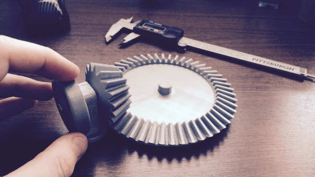
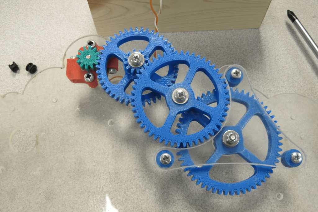
Много е важно да знаете ограниченията на вашия 3D принтер по отношение на размера на зъбите. Примера от снимката по-горе, на този пробен отпечатък на зъбно колело, е чудесна отправна точка. Проверете за точност и не забравяйте да използвате същия материал, който планирате да използвате за крайните зъбни колела.
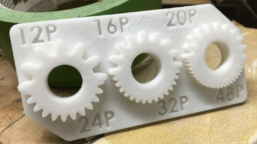
Размерът има значение
След като разберете до колко малък можете да стигнете, трябва също да разберете до колко голям можете да стигнете. По-големите зъбни колела позволяват по-големи зъби при същото съотношение. По-големите зъби също са по-здрави, могат по-добре да се справят с грешки в толеранса и са по-лесни за последваща обработка.
В тази бележка имайте предвид ширината на лицето, която е „височината“ на зъбно колело, ако е поставено плоско върху маса. Често дефинирана с помощта на различни практически правила, ширината е пряко свързана със силата на предавката и следователно трябва да бъде добре обмислена.
Присъединяване към вала
И накрая, помислете за присъединяването с вала. Това е как зъбните колела ще бъдат прикрепени към какъвто и вал да използвате. Този интерфейс играе основна роля в прехвърлянето на движение и е много вероятно да бъде точка на повреда във вашия дизайн, тъй като валовете обикновено се правят от метал, особено в двигателите.
Некръгъл присъедините, като шестоъгълник, е добра алтернатива, заедно с използването на сачмени лагери и други стойки за устройства.
Съвет #2: Дизайн
Željko Kanović чрез Research Gate)
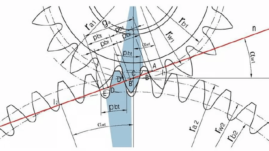
3D отпечатаните зъбни колела са лесни за прототипиране, но добре функциониращите зависят в голяма степен от някои ключови параметри. Модерният дизайн на съоръжения е 100-годишна дисциплина, която включва много физика. И въпреки че има много зъбни колела, еволвентното цилиндрично зъбно колело е най-често срещаното.
Когато проектирате класическо зъбно колело, важните параметри включват диаметри на стъпката, ъгли на натиск, челни ширини, централни разстояния, модули – списъкът може да продължи. Въпреки че няма да навлизаме в подробности тук, има много онлайн източници и интерактивни инструменти.
Независимо от това, най-основният принцип при проектирането на еволвентни зъбни колела е, че съпрягащата се повърхност между два зъба се появява в една точка. И това е възможно само с помощта на определен зъбен профил, направен от еволвенти на кръг, откъдето идва и името.
Проектирането на зъбно колело от нулата ще изисква отделяне на известно време за изучаване на параметрите на зъбното колело и използване на инструменти като Gear Generator. Този уебсайт създава цилиндрични зъбни колела въз основа на размери, въведени от потребителя. Тези подробности включват броя на зъбите, диаметъра на стъпката, диаметралната стъпка и ъгъла на натиск. Тъй като тези термини са малко специфични, ще ви трябват известни познания за зъбни колела, за да използвате успешно Gear Generator. Въпреки това, ако един параметър бъде променен, всички свързани размери ще бъдат променени пропорционално от уебсайта, така че функциониращо оборудване ще бъде произведено независимо от всичко. След като зъбните колела са проектирани в Gear Generator, те могат да бъдат изтеглени като DXF или SVG файл.
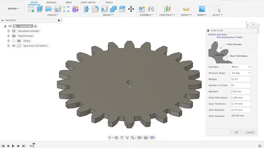
Gear Generator не е единствената удобна опция, която можете да използвате, за да генерирате зъбни колела. Fusion 360 има налична добавка Spur Gear, която изисква познаване на няколко параметри на дизайна в допълнение към тези, споменати за Gear Generator. Необходими са стойности за модул, хлабина и радиус на заобляне, което прави добавката Spur Gear гъвкава, но малко по-взискателна за създаване на зъбни колела.
Ако сте начинаещ, Tinkercad също може да бъде полезна опция. Можете да използвате програмата за създаване на цилиндрични зъбни колела, които са налични в библиотеката Shapes. Това е най-простият вариант, който споменахме, и са необходими значително по-малко параметри за създаване на зъбни колела. Само имайте предвид, че може да е необходимо тестване, за да се гарантира, че продуктът работи правилно, тъй като резултатите обикновено са по-малко точни. В противен случай прости дизайни на съоръжения за нови проекти могат да бъдат получени чрез онлайн хранилища като McMaster Carr, 3DContentCentral и GrabCAD.
За тези, които търсят резервни части, Stephan от CNC Kitchen канала в YouTube има видеоклип, който обхваща как да проектирам резервна предавка с помощта на обратно инженерство и добавка Fusion 360.
Съвет #3: Материали
Нека си признаем: 3D отпечатаните зъбни колела никога няма да бъдат толкова здрави или издръжливи, колкото шприцованите или машинно обработени части. Въпреки това, като се има предвид голямото разнообразие от пластмаси, налични за 3D печат, има много приложения, за които 3D печатът може да бъде подходящ или дори превъзходен по функционалност.
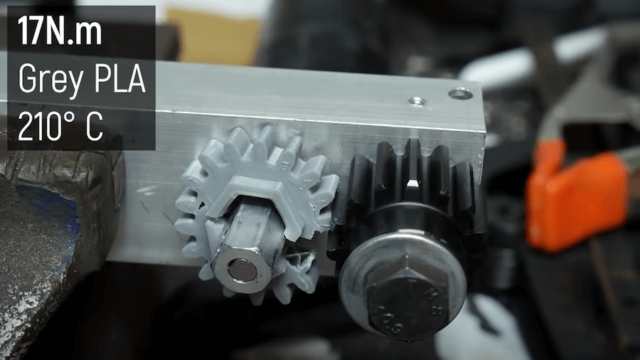
По отношение на издръжливостта, Nylon ( Полиамид) е първият избор, особено за работа без смазване. Въпреки че е сравнително труден за 3D отпечатване, полиамида има силата и гъвкавостта, необходими за направата на дълготрайни пластмасови зъбни колела.
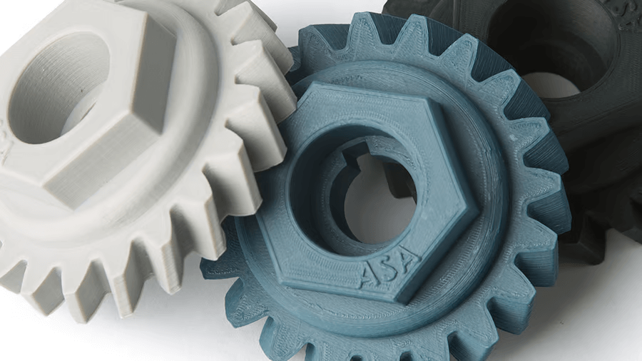
За да намалите неприятностите при печат, по-често срещаните материали за 3D печат, като PLA+ ABS или PETG, също могат да бъдат добър избор. Те се препоръчват пред по-популярния PLA, чуплив материал, който лесно се “щраква” при напрежение. PLA+ се препоръчва, защото предлага подобрена здравина и гъвкавост, както и може да се използва за функционални части. Частите от PLA+ са склонни да осигуряват повече гъвкавост и да издържат на натиск по-добре от традиционните PLA, което ги прави предпочитани за устройства за 3D печат.
PETG е по-добър вариант от PLA, тъй като няма да се счупи толкова лесно под натиск и има добра устойчивост на топлина, генерирана от триене.
Съвет #4: 3D печат
Най-накрая е време да материализирате своите съоръжения. Ето няколко неща, които трябва да имате предвид по отношение на 3D принтирането:
- Ориентация: Отпечатайте зъбни колела с лицето надолу. Начинът, по който слоевете се отлагат в тази ориентация ще направи зъбите по-здрави.
- Охлаждане на части: Особено в случай на PETG, включването на вентилатора за охлаждане на части може действително да отслаби 3D разпечатките. Изключването му позволява на слоевете да се разстопят заедно и увеличава якостта по оста Z.
- Равно легло: Уверете се, че имате перфектно нивелирано печатно легло. Когато печатате зъбни колела с лицето надолу, всяка неравност в леглото ще създаде изкривявания, които вероятно ще повлияят на функционалността.
- Височина на първия слой: Коригирането на началната височина на слоя е друг начин за подобряване на точността на частите. Увеличаването на първоначалната височина на слоя с една стъпка по-високо, например до 0,25 mm за 0,2 mm височина на слоя, може да намали “слонския крак” и да подобри функционалността. Ако дюзата е твърде близо до леглото, първият слой ще излезе смачкан и ще генерира отклонения на зъбите, които няма да позволят правилното свързване. Като алтернатива обмислете използването на rafts.
- Височина на слоя: Въпреки че напрежението е поставено върху XY-осите (ако приемем, че зъбното колело е отпечатано с лицето надолу), височината на слоя все още може да повлияе на цялостната здравина на частта. По-ниските височини на слоя, като 0,1 до 0,15 mm, ще направят по-здрава и по-хомогенна структура.
- Температура на горещия край: По-високата температура на горещия край ще подобри адхезията на слоя, подобно на начина, по който намалява скоростта на вентилатора за охлаждане на частта. 210-220 °C е добра начална точка за PLA, а 230-250 °C е добра за PETG, въпреки че е важно да се има предвид, че различните марки имат различни препоръчани от производителя настройки.
- Запълване: Като една от най-важните настройки за печатащи зъбни колела, правилният пълнеж значително ще подобрете здравината на частта и потенциално спестява много разочарование. Препоръчително е да увеличите процента от 50 до 100% и да използвате cubic, gyroid, или някакъв друг силен пълнеж модел.
- Печатни аномалии: Елиминирайте петна, нанизвания. Тези дефекти в повърхностите на зъбите ще доведат до неправилно зацепване на зъбните колела.
- Други настройки на секцията: Например по-високите температури на дюзите ще направят слоевете по-добри залепени.
- Последваща обработка: 3D отпечатаните зъбни колела често изискват известна последваща обработка, за да бъдат почистени и готов за употреба. Може да се наложи да използвате нож, за да почистите зъбите и е добра идея да шлайфате части с пила или шкурка, за да премахнете неточностите и малките дефекти.
- Отгряване: Въпреки че не е настройка, която можете да промените във вашия слайсер, отгряването е техника за последваща обработка, която може да накара 3D разпечатките да функционират по-скоро като шприцовани части. Чрез повторното разтопяване на пластмасата е възможно частта да стане по-хомогенна и да има еднаква якост по всички оси. Това е особено ефективно за PETG, въпреки че може да направи частите от PLA+ по-чупливи.
Повечето съвети по-горе се отнасят до цялостното калибриране на принтера. Като алтернатива, ако искате да оставите отпечатването на професионалистите, можете да опитате услуга за 3D печат на 3MG Bonev Ltd.
Оборудвай се
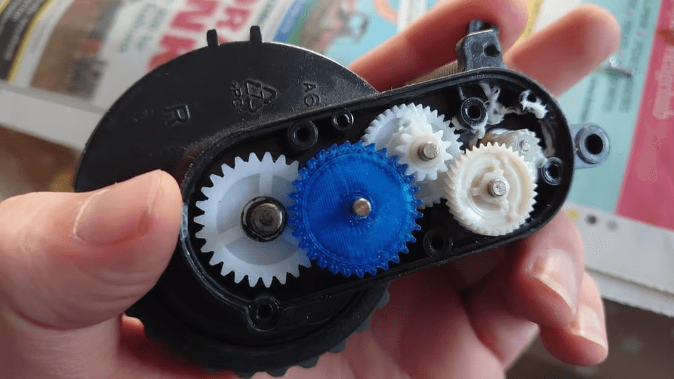
3D отпечатаните зъбни колела са осъществими и могат да отговарят на много различни цели. Можете да намерите вдъхновение и много примери за тях в интернет. Едно често срещано приложение е 3D отпечатване на персонализирани съоръжения за хобита като RC автомобили. Възможно е също така да отпечатате 3D зъбни колела за конкретни инструменти, които правите. За своето дърводелско менгеме с двойно зъбно колело.
Друга често срещана причина за 3D отпечатване на зъбни колела е ремонт на счупени части. Зъбни колела, които са се повредили от продължителна употреба, могат да бъдат поправени, запазвайки непокътнатите части на компонента от боклука. Например RWGresearch 3D отпечата резервно зъбно колело за своя мотоциклетен скоростомер. Има още повече приложения за зъбни колела за 3D печат, но това са някои чудесни примери за това какво е възможно.
Независимо от крайната употреба, надяваме се, че това ръководство е предоставило достатъчно информация, за да ви насърчи и помогне да направите тези класически механични компоненти.
0 Comments